Transmitter
The DP transmitter (DPTX) consists of two main layers: the policy maker (PM) and link layer (LNK). The policy maker is responsible for communication with the downstream DP sink device, training the link, and controlling the link layer.
The DPTX diagram is shown in Figure 1.

Figure 1: DPTX diagram
The DPTX parameters are shown in the table below
| Name | Type | Description | Values |
|---|---|---|---|
| P_VENDOR | String | Vendor | AMD, ALTERA, LSC |
| P_BEAT | Integer | Beat value | 50 |
| P_SDP | Bool | SDP support | 0, 1 |
| P_LANES | Integer | Number of lanes | 2, 4 |
| P_SPL | Integer | Symbols per lane | 2, 4 |
| P_PPC | Integer | Pixels per clock | 2, 4 |
| P_BPC | Integer | Bits per component | 8, 10 |
The DPTX signals are listed in the table below;
| Name | Clock | Description | Width |
|---|---|---|---|
| SYS_RST_IN | SYS_CLK | System reset | 1 |
| SYS_CLK_IN | SYS_CLK | System clock (50 MHz) | 1 |
| HOST_IF | SYS_CLK | Host interface | - |
| HOST_IRQ_OUT | SYS_CLK | Host interrupt | 1 |
| AUX_EN_OUT | SYS_CLK | AUX channel enable | 1 |
| HOST_IRQ_OUT | SYS_CLK | AUX channel transmit | 1 |
| HOST_IRQ_OUT | SYS_CLK | AUX channel receive | 1 |
| HOST_IRQ_OUT | SYS_CLK | Hot Plug Detect | 1 |
| HOST_IRQ_OUT | SYS_CLK | Heartbeat | 1 |
| HOST_IRQ_OUT | VID_CLK | Video clock | 1 |
| HOST_IRQ_OUT | VID_CLK | Video clock enable | 1 |
| HOST_IRQ_OUT | VID_CLK | Video vertical sync | 1 |
| HOST_IRQ_OUT | VID_CLK | Video horizontal sync | 1 |
| HOST_IRQ_OUT | VID_CLK | Video red | P_PPC * P_BPC |
| HOST_IRQ_OUT | VID_CLK | Video green | P_PPC * P_BPC |
| HOST_IRQ_OUT | VID_CLK | Video blue | P_PPC * P_BPC |
| HOST_IRQ_OUT | VID_CLK | Video data enable | 1 |
| HOST_IRQ_OUT | SYS_CLK | Secondary data packet clock | 1 |
| HOST_IRQ_OUT | SYS_CLK | Secondary data packet ready | 1 |
| HOST_IRQ_OUT | SDP_CLK | Secondary data packet start | 1 |
| HOST_IRQ_OUT | SDP_CLK | Secondary data packet end | 1 |
| HOST_IRQ_OUT | SDP_CLK | Secondary data packet data | 32 |
| HOST_IRQ_OUT | SDP_CLK | Secondary data packet valid | 1 |
| HOST_IRQ_OUT | LNK_CLK | Link clock | 1 |
| HOST_IRQ_OUT | LNK_CLK | Link data | P_LANES * P_SPL * 11 |
Video Interface
The DPTX has a native video interface and supports 2 or 4 pixels per clock. All video signals (prefixed with VID_) The DPTX has a native video interface. The interface can support 2 or 4 pixels per clock. The video interface signals listed in the signal table have the prefix VID_ All video signals are high active. The video clock (VID_CLK_IN) runs at the pixel clock divided by the pixels per clock (2 or 4). For example with video resolution 1080p60 the pixel clock is 148.5 MHz. In 2 pixels per clock configuration the video clock runs at 74.25 MHz. It has a frequency of 37.125 MHz in 4 pixels per clock. The video clock must be stable and is generated by a PLL. The DPTX can support any video timing as long as the horizontal video timing is dividable by the number of pixels per clock (2 or 4). The figures below shows the video timing and pixel mapping.
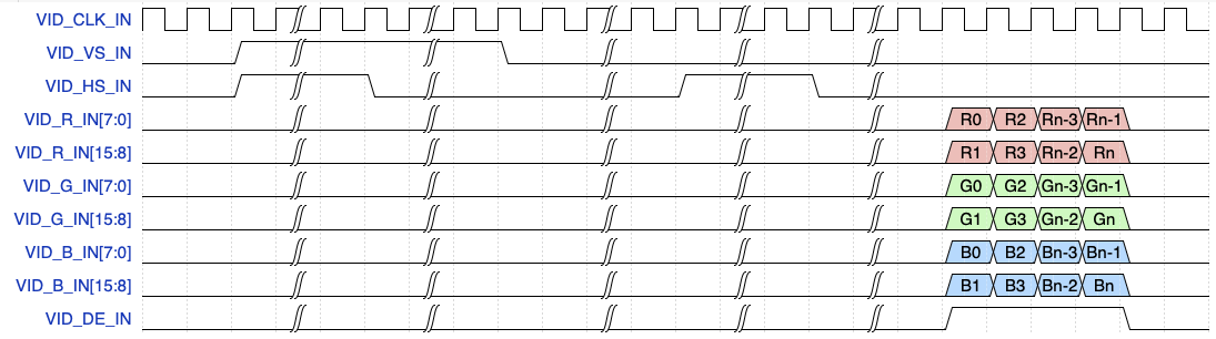
Figure 2: Video timing - 2 pixels per clock (click on the image to enlarge it)
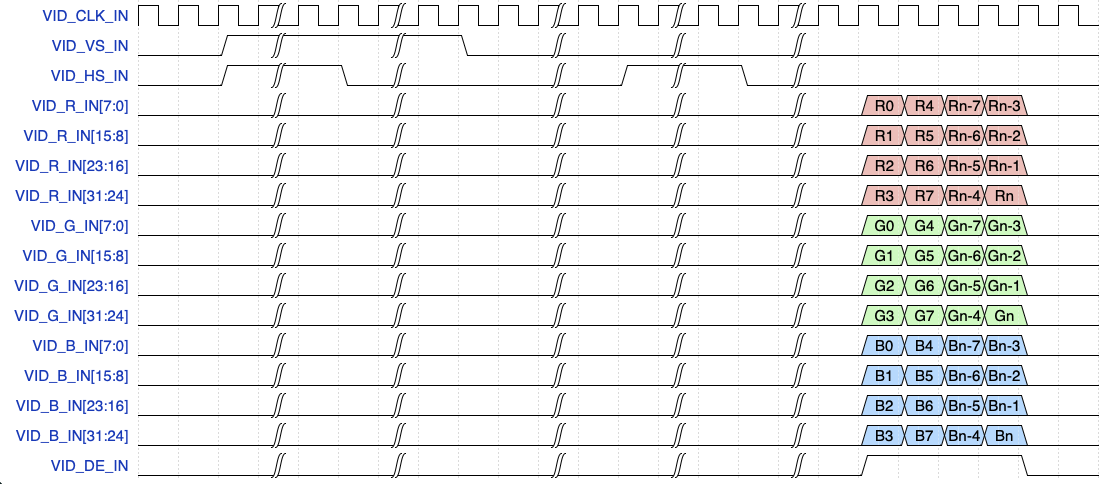
Figure 3: Video timing - 4 pixels per clock (click on the image to enlarge it)
Video clocking
The transmitter can support any video resolution. The table lists the video clocks for SD/HD video resolutions. The video clock is generated by the user.
| Resolution | Pixels-per-clock | Frequency (MHz) |
|---|---|---|
| 1280 x 720p | 2 | 37.125 |
| 1280 x 720p | 4 | 18.562 |
| 1920 x 1080p | 2 | 74.25 |
| 1920 x 1080p | 4 | 37.125 |
| 2560 x 1440p | 2 | 148.5 |
| 2560 x 1440p | 4 | 74.25 |
| 3840 x 2160p | 2 | 297 |
| 3840 x 2160p | 4 | 148.5 |