Encoder
The JPEG encoder converts uncompressed YCbCr video streams into fully compliant baseline JPEG images with
deterministic latency. The architecture is optimized for real-time video with support up to 4Kp60.
The encoder implements:
- 8×8 block-based Discrete Cosine Transform (DCT)
- Quantization with a host programmable table, based on the standard tables of ISO/IEC 10918-1 Annex K
- Baseline Huffman entropy encoding across eight parallel lanes
The core runs in two clock domains. The host side (SYS_CLK_IN) holds the APB interface and the
register file. The datapath (JPEG_CLK_IN) holds everything from the pixel input to the
codestream output and runs at the video rate. The controller carries the configuration, the JPEG header and
the bandwidth counters across the boundary.
Architecture
Pixels enter on the left and are gathered into 8×8 blocks by the line buffers. From there the blocks pass through the transform, the quantizer and the zig-zag reorder as a continuous stream, one row or column of eight coefficients per clock. The entropy encoder turns those coefficients into the Huffman coded bitstream, and the codestream mux prefixes the JPEG header that the host wrote at configuration time.
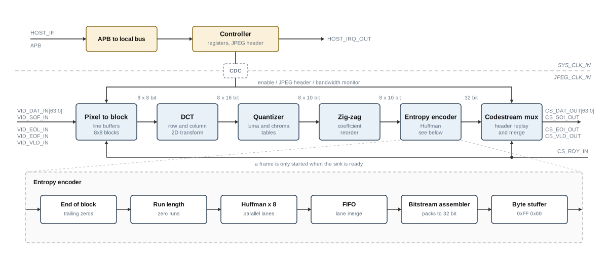
Figure 1: JPEG encoder architecture (click on the image to enlarge it)
-
Pixel to block
prt_jpeg_enc_pix2blkSplits the incoming 64-bit word into its luma and chroma components and writes them into three line buffers. Once eight lines are in, the buffers are read back as 8×8 blocks, one row of eight samples per clock, and the three components are interleaved into MCU order.
-
DCT
prt_jpeg_enc_dctA two dimensional transform built from two one dimensional stages with a transpose buffer in between. The row stage takes a row of samples per clock, the transpose buffer turns the block, and the column stage produces a column of 16-bit coefficients per clock.
-
Quantizer
prt_jpeg_enc_qntScales the coefficients with a table of luma and chroma constants and clamps the result to 10 bits. The table is held in a dual clock RAM that the host writes over APB, so the image quality is a run time setting rather than a synthesis time one. It is stored twice: the host always writes the buffer that is not in use, and the active one only changes at the start of a frame, so loading a new table cannot disturb the frame that is being encoded.
-
Zig-zag
prt_jpeg_enc_zzReorders the block from column order into the zig-zag sequence the JPEG standard expects, so that the coefficients leave in increasing frequency order.
-
Entropy encoder
prt_jpeg_enc_eeDetects the end of block, run length codes the zero runs, and Huffman codes the result in eight parallel lanes. A FIFO merges the variable length codes of those lanes back into one stream, the bitstream assembler packs them into 32-bit words and the stuffer inserts the 0x00 byte after every 0xFF, as the standard requires.
-
Codestream mux
prt_jpeg_enc_csmHolds the JPEG header in a small RAM and replays it at the start of every image, then passes the entropy coded data straight through to the sink. It also measures the sink bandwidth over each image.
| Name | Type | Description | Values |
|---|---|---|---|
| P_VENDOR | String | Vendor | LSC |
| P_FAMILY | String | Device family (Lattice only) | LFCPNX |
| P_HWIDTH | Integer | Maximum horizontal line width. Sizes the line buffers, so it sets the widest image the core can take. Any narrower image is encoded without changes. | MAX 3840 |
| P_PPC | Integer | Pixels per clock | 4 |
| P_BPC | Integer | Bits per component | 8 |
| Name | Clock | Description | Width |
|---|---|---|---|
| SYS_RST_IN | SYS_CLK | System reset | 1 |
| SYS_CLK_IN | SYS_CLK | System clock | 1 |
| JPEG_RST_IN | JPEG_CLK | JPEG reset | 1 |
| JPEG_CLK_IN | JPEG_CLK | JPEG clock | 1 |
| HOST_IF | SYS_CLK | Host interface | APB |
| HOST_IRQ_OUT | SYS_CLK | Host interrupt | 1 |
| VID_SOF_IN | JPEG_CLK | Start of frame | 1 |
| VID_DAT_IN | JPEG_CLK | Data | 64 |
| VID_EOL_IN | JPEG_CLK | End of line | 1 |
| VID_EOF_IN | JPEG_CLK | End of frame | 1 |
| VID_VLD_IN | JPEG_CLK | Valid | 1 |
| CS_RDY_IN | JPEG_CLK | Ready | 1 |
| CS_SOI_OUT | JPEG_CLK | Start of image | 1 |
| CS_EOI_OUT | JPEG_CLK | End of image | 1 |
| CS_DAT_OUT | JPEG_CLK | Data | 64 |
| CS_VLD_OUT | JPEG_CLK | Valid | 1 |
Video Interface (VID)
The JPEG Encoder IP-core provides a high-throughput parallel video input interface. The interface accepts unpacked YCbCr 4:2:2 pixel data and supports multi-pixel-per-clock operation for efficient processing of high-resolution video streams. The video interface signals listed in the signal table have the prefix VID_.
One clock carries four luma samples and two chroma pairs, so a full 16 pixel MCU row arrives in four clocks.
VID_SOF_IN is asserted ahead of the first word of a frame and clears again when that word is
accepted. VID_EOL_IN marks the last word of a line and VID_EOF_IN the last word of
the frame. The diagram below shows the timing waveform and the byte lane mapping.
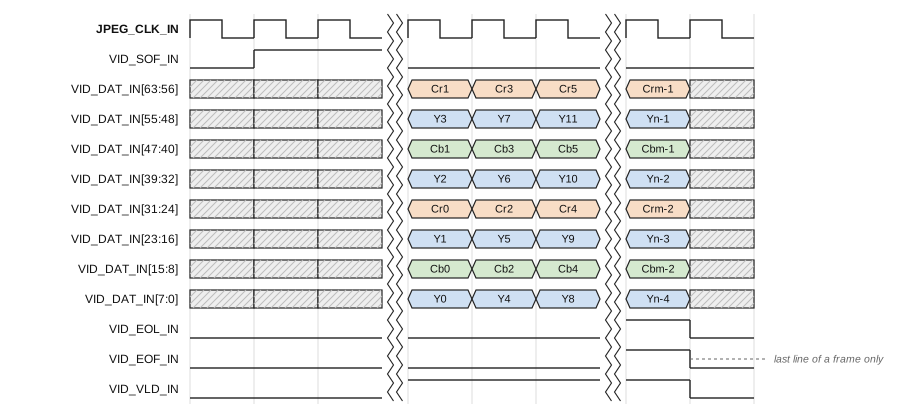
Figure 2: Video interface timing and pixel mapping (click on the image to enlarge it)
The video source cannot be stalled, so the core has no backpressure towards it. A frame is only started when the codestream sink is ready; if it is not, that frame is dropped as a whole rather than encoded part way.
Codestream Interface (CS)
The codestream interface provides the compressed JPEG bitstream output via a standard AXI4-Stream interface.
This allows seamless integration with DMA engines, memory controllers, PCIe blocks, NVIDIA Hololink pipeline,
or other AXI-based FPGA infrastructure.
Output Characteristics:
- 64-bit output stream, with
CS_SOI_OUTandCS_EOI_OUTframing each image - Variable bitrate (depends on quantization and image content)
- Fully compliant baseline JPEG bitstream
- Includes markers (SOI, APP0, DQT, SOF0, DHT, COM, SOS, EOI)
The codestream is not buffered. The header is replayed from a small RAM at the start of every image and the entropy coded data is gathered from 32 into 64 bits and handed straight to the sink. Writer and reader both move at most one word per clock, so with the sink ready there is nothing for a buffer to smooth out.
If the sink is not ready when entropy data arrives, that data is lost. This is handled explicitly rather than hidden: the rest of the image is abandoned and an end of image marker is appended, so the host receives a codestream that is short and detectably truncated instead of complete and silently wrong. The next image starts clean. The bandwidth counters described below exist to catch exactly this condition.
Register map
The register file sits behind the APB interface. The driver wraps these registers, so an application does not normally touch them directly.
| Offset | Name | Access | Description |
|---|---|---|---|
| 0x00 | ID | R | Identification. Bits [15:0] read 0x3478, [23:16] the major version and [31:24] the minor version. |
| 0x04 | CTL | R/W | Control. Bit 0 runs the encoder, bit 1 enables the interrupt. Bit 2 is used by the driver and always reads back as zero. |
| 0x08 | STA | R | Reserved. Kept so that the registers behind it keep their offsets. |
| 0x0C | HDR_LEN | W | Length of the JPEG header in bytes. Writing it starts the header transfer. |
| 0x10 | HDR_DAT | W | JPEG header data, written four bytes at a time. |
| 0x14 | HWIDTH | R/W | Horizontal width in pixels. The encoder derives the number of MCUs in a line from it, so it has to agree with the width declared in the SOF0 header; the driver writes both from the same value. The P_HWIDTH parameter is only the upper bound the line buffers are built for. |
| 0x18 | VHEIGHT | R/W | Vertical height in lines. Not used by the encoder at present, which takes the end of the frame
from VID_EOF_IN; written for consistency with the SOF0 header. |
| 0x1C | MON_CLKS | R | Clocks of the last video frame, measured from VID_SOF_IN to VID_EOF_IN. |
| 0x20 | MON_VID | R | Video words that arrived during the last frame. A word is eight bytes. |
| 0x24 | MON_CS | R | Codestream words handed to the sink during the last image, counted from CS_SOI_OUT
to CS_EOI_OUT. A word is eight bytes, so MON_VID divided by MON_CS is the
compression ratio. |
| 0x28 | QNT_DAT | W | Quantization table data, written by prt_jpeg_enc_cfg. The format is part of the driver interface. The table has no reset value, so this has to be done before the encoder is started. |